
Introduction to parasitIC capacitance in PCB layout
A. PCB board is composed of multiple conductors in parallel, such as traces, separated by insulators These traces, together with dielectric data, form capacitors, resulting in unnecessary parasitic capacitance or stray capacitance effects
The parasitIC components in a PCB can be parasitic capacitors, parasitic resistors, and parasitic inductors. When the traces are close, the parasitic capacitance effect is particularly prominent in the high-frequency board. This effect is unnecessary and will affect the function of the equipment. It can cause crosstalk, EMI, and signal integrity issues. PCB designers dealing with high frequency, high data rate and mixed signal boards must consider parasitic capacitance and inductance effects when designing PCB layout.
In the next section, we will understand the definition of parasitic capacitance and its impact on the circuit board.
What is the parasitic capacitance in the PCB?
Closely placed PCB wires form a virtual capacitor, generating parasitic capacitance effect
The parasitic capacitance or stray capacitance is the result of the virtual capacitance formed between two recording traces separated by a dielectric. This is caused by the potential difference generated when the current carrying trace is closed. For more information, read the role of circuit current capacity in PCB design.
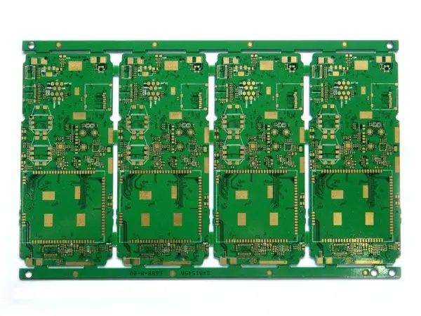
Circuit board

This effect is possible even if the conductor is properly insulated. Since there is no ideal circuit, parasitic capacitance cannot be avoided.
Charging and discharging loop in capacitor.
Parasitic capacitance is an inherent characteristic of conductor. It is the storage amount of potential changes in each tissue. The calculation formula of parasitic capacitance is C=q/v. Wherein, C is the capacitance organized by farad, v is the voltage organized by volt, and q is the charge organized by coulomb.
For a constant electrical signal that does not change with time, dv/dt=0, which means that the potential does not change; Recall that i=0.
If there is a capacitor in the circuit loop, dv/dt will converge to a fixed value, that is, the potential changes and current is generated; Recall that i – 0.
Track capacitance calculation
The capacitance of parallel plate capacitor is given by C=(kA/11.3d) pF. Where, C is the capacitance, A is the area of the plate, the organization is cm 2, k is the relative dielectric constant of the plate data, d is the distance between the plates, and the organization is cm.
Modeling of PCB parasitic components at high frequencies.
Parasitic capacitance effect is a problem in High Frequency Circuit Boards. In low-frequency operation, parasitic components can be ignored because they do not really affect the system function. Each pad on the circuit board has its parasitic capacitance, and each track has its parasitic inductance. Parasitic resistance is added to the pad to stimulate infrared loss. Parasitic capacitance may exist between the conductors in PCB, bare board, PCBA, assembly board and component package, especially surface mount devices (SMDs).
Since the inherent capacitor board has potential difference, there is an opportunity for current flow. It does not matter whether the charge is stored between the capacitor plates; The current will flow only if there is a potential difference. Once the potential difference increases, it can be observed that the electron flow to the load in the expected signal path decreases accordingly, which has a negative impact on signal integrity.
What is the difference between stray capacitance and parasitic capacitance?
The term stray capacitance is often used interchangeably with parasitic capacitance. However, parasitic capacitance indicates that it will hinder circuit operation, while stray capacitance indicates how to introduce unnecessary capacitance.
What is stray capacitance?
Due to the virtual capacitance formed between two PCB conductors and the influence of the surrounding environment, stray capacitance can not always be detected. This is calLED stray capacitance.
What is the parasitic resistance in the PCB?
Parasitic resistance exists in series along the line or as a shunt between conductive components.
What is the parasitic inductance in the PCB?
Parasitic inductors exist along the track, showing the behavior of storing and dissipating electrical energy, just like the actual inductor. All conductors are inductive. At high frequencies, even the inductance of relatively short conductors or PCB traces may be important.
Parasitic capacitance effects may be crosstalk and noise, poor output echo, and the formation of resonant circuits. This, we must pay attention to the overall design of PCB, especially the layout. When one conductor is placed next to another, great care should be taken to make a good layout.
Parasitic components include inductors formed by package leads, long traces, pad to ground, pad to power plane, and pad to line capacitors, including interactions with vias. Parasitic components are considered as parasitic components that threaten circuit effectiveness. Unwanted and unavoidable, but controllable at the same time.
In high-speed circuits, a few tenths of pickup trucks are enough to affect circuit efficiency. For example, a 1pF parasitic capacitance at the reverse input will result in a 2dB peak in the frequency domain. If it exceeds 1pF, it will cause instability and oscillation.
Capacitors block low-frequency and DC signals and transmit high-frequency signals in electronic circuits This characteristic of capacitors passing high-frequency signals (the speed at which capacitors discharge is another reason they are used to replace much slower batteries) is the cause of stray capacitance problems in high-speed circuits. For the conductor, stray capacitance will introduce electromagnetic interference or noise, which can be propagated along the conductor and cable or transmitted to adjacent traces nearby In general, it is not possible to eliminate stray capacitance However, there are some effective methods to alleviate this situation
Avoid parallel wiring: When parallel wiring occurs, the area between two metals is the largest, and the capacitance between them is the largest.
然后
聯(lián)系
電話熱線
13410863085Q Q

微信

- 郵箱


